
STM32 RTC functions
Published:
Introduction
This post intends to explore the functions of the Real Time Clock (RTC) of STM32 microcontrollers. This time we also use CubeMX, the powerful code generator for STM32 MCUs.
The purpose for this post is to get familiar with the RTC for uCs and intend to use this for my next step of the research project.
My next work is to design a sensor node that could wakeup every minute (or other time period), and do the following functions:
- generate PWM waveforms to drive the LC shutter for a specific time (maybe 10-15 seconds).
- read data from the PIR sensor and temperature sensor
- send the data to the server (via Bluetooth, Wifi, ZigBee, etc)
- enter sleep mode.
Also, during the sleep mode, the MCU should be able to woken up by the motion of the person. This is done by attach an external pin from PIR sensor to the MCU.
Concerns
Right now the PIR sensors which is integrated with LC shutter is the AMN24112 analog PIR sensor, which require ADC to poll the signals. ADC consumes high power. If we really stick to this sensor model, it is difficult to wake up the MCU since the MCU is sensitive to the edge of the attached pin, but the analog signals from the PIR sensor is not analog.
Solutions:
- USe a second digital PIR sensor and attach the output pin to the wakeup pin.
- Add an comparator that could generate edge once the signal from the analog sensor reached certain level.
Alarm
Goal – Use an LCD-SSD1306, to show the calendar in real time, then add an “alarm” sign when the second reach 0 every minute. The “alarm” sign would disappear after 5 seconds.
Setup
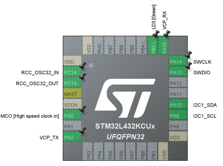
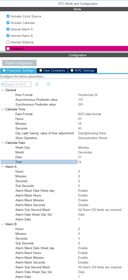
After create the new project, setup the RTC and I2C1 as follows. Here we use two alarms, ALARMA and ALARMB. Note that the Alarm masks for date, hour, minute are enabled, to ignore the number in these fields. Remember to check the NVIC setting.
Code
Requirements:
- SSD1306 library. controllerstech.com/oled-display-using-i2c-stm32/
- Follow the instructions in this video to setup the correct path to the driver files.
After generaing code, code as followed:
Before main function, declare two RTC Type Def for date and time:
char CalendarString[50];
char TimeString[50];

RTC_DateTypeDef sDate;
RTC_TimeTypeDef sTime;
In main function:
Set the start time and date
  // set time and date
  sTime.Hours = 23;
  sTime.Minutes = 59;
  sTime.Seconds = 45;
  sDate.Year = 19;
  sDate.Month = RTC_MONTH_DECEMBER;
  sDate.Date = 31;

  HAL_RTC_SetTime(&hrtc, &sTime, RTC_FORMAT_BIN);
  HAL_RTC_SetDate(&hrtc, &sDate, RTC_FORMAT_BIN);
In while loop:
while (1)
  {
    /* USER CODE END WHILE */

    /* USER CODE BEGIN 3 */
    // update the sTime and sDate.
	  HAL_RTC_GetTime(&hrtc, &sTime, RTC_FORMAT_BIN);
	  HAL_RTC_GetDate(&hrtc, &sDate, RTC_FORMAT_BIN);

    // combine date and time to two strings
	  sprintf(CalendarString, "20%02d/%02d/%02d", sDate.Year, sDate.Month, sDate.Date);
	  sprintf(TimeString, "%02d:%02d:%02d", sTime.Hours, sTime.Minutes, sTime.Seconds);

	  // LCD display and update
	  SSD1306_GotoXY(0, 0);
	  SSD1306_Puts(CalendarString, &Font_11x18, 1);
	  SSD1306_GotoXY(0, 20);
	  SSD1306_Puts(TimeString, &Font_11x18, 1);
	  SSD1306_UpdateScreen();

	  HAL_Delay(1000);

  }
At the end, add two callback functions
void HAL_RTC_AlarmAEventCallback(RTC_HandleTypeDef *hrtc)
{
  /* Prevent unused argument(s) compilation warning */
  UNUSED(hrtc);

  /* NOTE : This function should not be modified, when the callback is needed,
            the HAL_RTC_AlarmAEventCallback could be implemented in the user file
   */
  //HAL_GPIO_TogglePin(GPIOB, GPIO_PIN_3);

  // update alarm when the second is 0
  SSD1306_GotoXY(0, 40);
  SSD1306_Puts("Alarm", &Font_11x18, 1);
  SSD1306_UpdateScreen();
}

void HAL_RTCEx_AlarmBEventCallback(RTC_HandleTypeDef *hrtc)
{
  /* Prevent unused argument(s) compilation warning */
  UNUSED(hrtc);

  /* NOTE : This function should not be modified, when the callback is needed,
            the HAL_RTCEx_AlarmBEventCallback could be implemented in the user file
   */
  // update alarm when the second is 5
  SSD1306_GotoXY(0, 40);
  SSD1306_Puts("        ", &Font_11x18, 1);
  SSD1306_UpdateScreen();
}
Demo
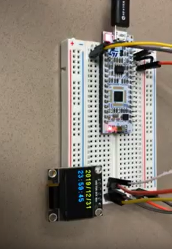
From the demo video, we could see that when the board start at 2019/12/31 23:59:45. When the time reached 2020/1/1 00:00:00, the “alarm” sign apears. After 5 seconds, it disappears. Not shown in the video, the “alarm” sign would appear every minute when the second is at 0, and disappear after 5 seconds.
Wakeup from standby mode
Low power mode of STM32
From the datasheet, the low power power is summerized in the table. 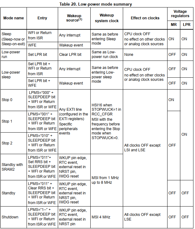 Low power mode
Besides the total shutdown, standby mode consumes the lowest power. 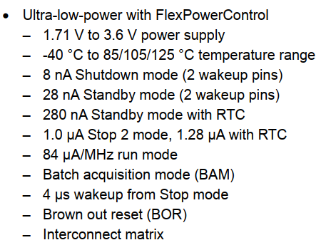 Low power consumption
The feature of the standby mode is that when it wakes up, the MCU would run from the start (act like a reset). The SRAM would be cleared except the registers in backup domain.
Code
The corresponding sample code is as follows.
In main function (before while loop):
/* USER CODE BEGIN 2 */

  /* check the standby mode status */
  if (__HAL_PWR_GET_FLAG(PWR_FLAG_SB) != RESET){
	  // clear SB flag
	  __HAL_PWR_CLEAR_FLAG(PWR_FLAG_SB);
  }

  // toggle LED
  HAL_GPIO_WritePin(GPIOB, GPIO_PIN_3, GPIO_PIN_SET);
  HAL_Delay(1000);
  HAL_GPIO_WritePin(GPIOB, GPIO_PIN_3, GPIO_PIN_RESET);

  // clear wakeup flag
  __HAL_PWR_CLEAR_FLAG(PWR_FLAG_WU);

  /*	Enable wakeup
   * 	The second parameter is the WakeupCounter
   * 	EXAMPLE 1:
   * 	the RTC is configured to use LSE (32.768kHz) as the clock source
   * 	The proposed wakeup time is 4 seconds.
   * 	Then the interval time of the counter is 1/(LSE/DIV).
   * 	Here, DIV is 16, t_interval = 1/(32768/16) = 1/2048 second
   * 	WakeupCounter = 4 seconds/t_interval = 8192 = 0x2000
   *
   * 	EXAMPLE 2: Clock source is RTC_WAKEUPCLOCK_CK_SPRE_16BITS, which is 1Hz
   * 	WakeupCounter = time_to_standby
   */
  HAL_RTCEx_SetWakeUpTimer(&hrtc, 0x2000, RTC_WAKEUPCLOCK_RTCCLK_DIV16);

  // enter standby mode
  HAL_PWR_EnterSTANDBYMode();


  /* USER CODE END 2 */